
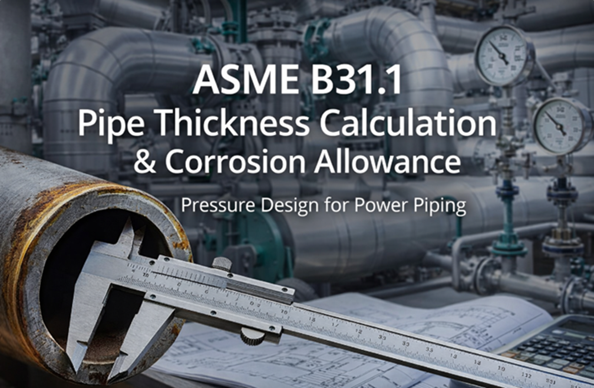
Learn how pipe wall thickness is calculated under ASME B31.1. Understand pressure design, corrosion allowance, mill tolerance, and real plant examples from main steam and boiler feedwater piping.
Table of Contents
Introduction
In piping engineering, pipe thickness is not chosen randomly, nor is it based only on experience or “what worked before.”
In power plants, refineries, oil & gas facilities, and chemical plants, pipe wall thickness is a safety-critical design decision governed by codes such as ASME B31.1 – Power Piping.
Many beginners believe that selecting a pipe schedule (for example, Schedule 40 or Schedule 80) automatically satisfies all design requirements. In real-world engineering, this assumption is dangerous and incorrect.
This article explains of ASME B31.1, focusing on:
- Pressure design philosophy
- Pipe thickness calculation
- Corrosion allowance
- Mill tolerance
- Why minimum required thickness is not the same as practical thickness
Examples from main steam lines and boiler feedwater piping are included to connect theory with actual plant practice.
This article also links logically to:
- Article 4 – Piping Materials
- Article 6 – Thermal Expansion and Stress Analysis
Purpose of Pressure Design in Piping Engineering
The primary purpose of pressure design is to ensure that a pipe can safely contain internal pressure throughout its design life without:
- Rupture
- Excessive deformation
- Progressive thinning due to corrosion or erosion
In ASME B31.1, pressure design ensures that:
- Hoop stress remains within allowable limits
- Long-term degradation is accounted for
- Manufacturing tolerances are considered
Pressure design is one of the first checks a piping engineer performs after identifying:
- Line number
- Line designation
- Fluid code
- Design pressure
- Design temperature
- Piping class
These parameters are usually defined on the P&ID and piping line list.
Why Minimum Thickness Alone Is Not Enough
One of the most common mistakes made by junior engineers is assuming that:
“If the calculated thickness is 6 mm, selecting a 6 mm pipe is acceptable.”
This approach ignores several real-world factors:
- Corrosion during service
- Mill tolerance (manufacturing variation)
- Future operating upsets
- Erosion due to high-velocity flow
ASME B31.1 requires that additional thickness allowances be added to the calculated minimum thickness to ensure long-term safety and reliability.
Parameters Used in Pipe Thickness Calculation
Pipe thickness calculation under ASME B31.1 depends on several interrelated parameters. Each must be selected carefully.
1. Design Pressure
Design pressure is the maximum internal pressure the piping system is expected to experience during normal or upset conditions.
It is not the normal operating pressure.
Examples:
- Main steam line operating at 160 bar → design pressure may be 170–180 bar
- Boiler feedwater operating at 200 bar → design pressure may be 210–220 bar
Design pressure is typically defined by:
- Process engineer
- Mechanical design basis
- P&ID notes
Using an incorrect design pressure directly results in an unsafe thickness calculation
2. Allowable Stress
Allowable stress is the maximum stress the pipe material can safely withstand at design temperature.
Key points:
- Allowable stress decreases as temperature increases
- It depends on the material specification (e.g., ASTM A106 Gr.B, ASTM A335 P91)
- Values are provided in ASME allowable stress tables
For example:
- Carbon steel allowable stress at 300°C is much lower than at ambient temperature
- High-alloy steels are selected primarily for higher allowable stress at elevated temperatures
This is why material selection and pressure design are tightly linked.
3. Outside Diameter (OD)
ASME B31.1 thickness calculations are based on the outside diameter, not nominal pipe size (NPS).
For example:
- NPS 10 pipe has a fixed OD of 273.05 mm
- Thickness changes with schedule, but OD remains constant
Using OD ensures consistency across different pipe schedules.
4. Weld Joint Efficiency
Weld joint efficiency accounts for:
- Type of weld (seamless vs welded)
- Extent of nondestructive examination (RT, UT)
Typical values:
- Seamless pipe → efficiency close to 1.0
- Welded pipe with full radiography → high efficiency
- Welded pipe with limited examination → reduced efficiency
In power piping, main steam and feedwater lines often require high weld quality, making weld joint efficiency a critical parameter.
Basic Concept of Pipe Thickness Calculation
The thickness calculation ensures that the hoop stress caused by internal pressure does not exceed allowable stress.
In simple terms:
- Higher pressure → thicker pipe
- Higher temperature → thicker pipe
- Lower material strength → thicker pipe
ASME B31.1 provides equations that relate:
- Design pressure
- Outside diameter
- Allowable stress
- Weld joint efficiency
The result is the minimum required wall thickness for pressure containment.
Corrosion Allowance
Why Corrosion Allowance Is Added
Corrosion allowance is added to account for:
- Internal corrosion
- Flow-accelerated corrosion
- Erosion
- Chemical attack
Even clean-looking fluids like water or steam can cause long-term wall thinning.
Corrosion allowance ensures that:
- The pipe remains safe at end of design life
- Inspection intervals remain manageable
- Sudden failures are avoided
Typical Corrosion Allowance Values in Power Piping
In power plants, typical corrosion allowance values are:
| Service | Typical Corrosion Allowance |
|---|---|
| Main steam | 0 to 1 mm |
| Boiler feedwater | 1 to 3 mm |
| Condensate lines | 1 to 2 mm |
| Blowdown lines | 3 mm or more |
Actual values depend on:
- Water chemistry
- Velocity
- Oxygen content
- Past plant experience
Mill Tolerance and Its Impact
Pipe manufacturers are allowed a negative thickness tolerance, typically:
- Up to 12.5% thinner than nominal thickness
This means:
- A 10 mm thick pipe may be supplied at 8.75 mm
- If corrosion allowance is not considered, failure can occur much earlier than expected
Therefore, piping engineers often:
- Add corrosion allowance
- Select a thicker pipe schedule
This is why calculated thickness ≠ selected thickness.
Minimum Thickness vs Practical Thickness
Let us clarify an important concept.
Minimum Required Thickness
- Calculated using ASME B31.1 equations
- Includes pressure requirement only
Required Thickness
- Minimum thickness + corrosion allowance
Nominal Thickness
- Actual thickness of the selected pipe schedule
In real projects:
- Engineers select a standard pipe schedule that exceeds required thickness
- Standardization reduces fabrication errors and cost
Practical Example: Main Steam Line
Service: Superheated steam
Design pressure: 170 bar
Design temperature: 540°C
Material: ASTM A335 P91
Steps followed by piping engineer:
- Identify design conditions from P&ID
- Select material based on temperature and creep strength
- Calculate minimum thickness for pressure
- Add corrosion allowance (often minimal for dry steam)
- Check mill tolerance
- Select next higher standard schedule
Result:
- Calculated thickness may be 18 mm
- Selected pipe may be 22 mm or 25 mm
Practical Example: Boiler Feedwater Piping
Service: High-pressure feedwater
Design pressure: 220 bar
Design temperature: 200°C
Material: Carbon steel or low-alloy steel
Challenges:
- Oxygen corrosion
- Flow-accelerated corrosion
- Continuous operation
Design approach:
- Higher corrosion allowance (2–3 mm)
- Conservative pipe schedule selection
- Close coordination with materials engineer
Common Thickness-Related Errors
- Using operating pressure instead of design pressure
- Ignoring corrosion allowance
- Forgetting mill tolerance
- Selecting pipe schedule before calculation
- Copy-pasting thickness from old projects without validation
- Ignoring future uprating possibilities
These errors often appear during:
- Construction stage
- Fitness-for-service evaluations
- Unexpected pipe leaks
Frequently Asked Questions (FAQs)
Q1: Is corrosion allowance mandatory in ASME B31.1?
Corrosion allowance is not optional in practical design. While values may be small for some services, ignoring it is unsafe engineering practice.
Q2: Can I use Schedule 40 for all power piping?
No. Many power piping services require Schedule 80 or higher due to pressure, temperature, or corrosion considerations.
Q3: Does thicker pipe always mean safer design?
Not necessarily. Excessive thickness increases thermal stress and support loads. Balance is required.
Q4: Where do I find design pressure and temperature?
From the P&ID, line list, piping class, and project design basis.
Final Thoughts
Pipe thickness calculation is one of the most fundamental responsibilities of a piping engineer. It combines:
Code knowledge
Material science
Plant experience
Engineering judgment
Understanding why minimum thickness is not enough separates a beginner from a professional piping engineer.