Learn piping isometrics step by step with clear explanations designed for beginners in piping engineering. This practical guide explains piping design using real plant examples, including P&ID interpretation, line numbering system, piping class, and material specification. Based on ASME B31.1 power piping and industry best practices used in oil and gas piping projects. Ideal for mechanical engineers, piping designers, and students who want to understand piping isometric drawings correctly.
Table of Contents
Introduction to Piping Isometrics in Piping Engineering
In Piping Engineering, one of the most important deliverables during detailed engineering and construction is the piping isometric drawing, commonly called a piping iso. Whether you are working in oil and gas piping, chemical plants, refineries, or power plants designed to ASME B31 codes, piping isometrics are the backbone of fabrication and erection activities.
As a mechanical engineer with more than 25 years of hands-on piping design experience, I can say confidently:
If a piping isometric is wrong, the pipe will be fabricated wrong — no matter how good your P&ID or 3D model is.
This article explains piping isometrics step-by-step, starting from basic concepts and gradually moving into real plant examples. The explanations are aligned with ASME B31.1 Power Piping philosophy and industry practice.
If you are new to piping design, this guide will help you connect P&ID → piping layout → piping isometric → fabrication clearly and practically.
What Is a Piping Isometric Drawing?
A piping isometric is a single-line 3D representation of a piping system that shows:
- Pipe routing in three dimensions
- Exact pipe lengths and cut lengths
- Fittings, flanges, valves, and specialty items
- Welding details
- Line number and piping class information
- Design pressure and design temperature
- Material specification
- Insulation and tracing requirements
Unlike P&IDs, which show process intent, piping isometrics show how the pipe will actually be fabricated and installed in the plant.
Relationship Between P&ID and Piping Isometric
Before creating a piping isometric, you must clearly understand the P&ID (Piping and Instrumentation Diagram).
P&ID Shows:
- Fluid type and flow direction
- Line number and fluid code
- Valves and instruments
- Design pressure and design temperature
- Piping class reference
Piping Isometric Shows:
- Physical routing of the pipe
- Dimensions and coordinates
- Weld numbers
- Spool breaks
- Elevations and slopes
👉 A piping isometric is always developed from an approved P&ID.
If the P&ID changes, the piping isometric must be updated.
(Internal link suggestion: “Learn how to read P&IDs for piping engineers”)
Understanding Line Designation and Line Numbering System
One of the first things you see on any piping isometric is the line number.
Typical Line Number Format:
12”-P-101-CS-150#-A
Explanation:
- 12” → Nominal Pipe Size (NPS)
- P → Fluid code (Process, Steam, Utility, etc.)
- 101 → Sequential line number
- CS → Material (Carbon Steel)
- 150# → Pressure rating
- A → Insulation or service identifier
This line designation system links the isometric to:
- P&ID
- Line list
- Stress analysis
- Material take-off (MTO)
⚠️ Beginners often ignore line numbers — never do that.
Line number mistakes cause wrong material procurement and rework.
ASME B31.1 Code Philosophy for Piping Isometrics
ASME B31.1 – Power Piping governs piping systems in:
- Power plants
- Boiler piping
- High-temperature steam lines
- Feedwater systems
While ASME B31.1 does not dictate how an isometric should look, it strongly influences:
- Design pressure
- Design temperature
- Allowable stresses
- Material specification
- Flexibility and expansion requirements
When preparing piping isometrics under ASME B31.1, special attention is given to:
- High temperature expansion
- Proper support spacing
- Drain and vent locations
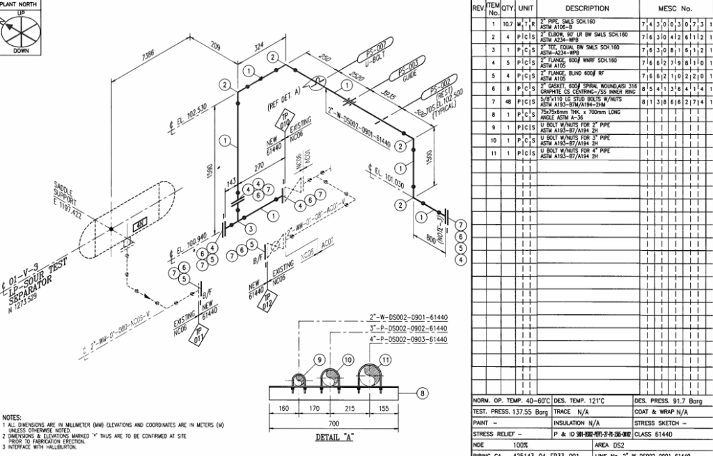
Key Information Shown on a Piping Isometric
Every piping isometric must clearly show the following:
1. Line Number and Piping Class
The piping class defines:
- Pipe material
- Fittings and flange rating
- Gasket type
- Bolting material
Example:
Piping Class: CS-150-A
This links directly to the piping material specification approved for the project.
2. Pipe Size, Schedule, and Material Specification
Example notation:
10” NB, SCH 40, ASTM A106 Gr.B
This ensures:
- Correct wall thickness
- Compliance with ASME B31 allowable stress limits
3. Design Pressure and Design Temperature
These are normally shown in the title block.
Example:
- Design Pressure: 45 barg
- Design Temperature: 425°C
These values come directly from the P&ID and line list.
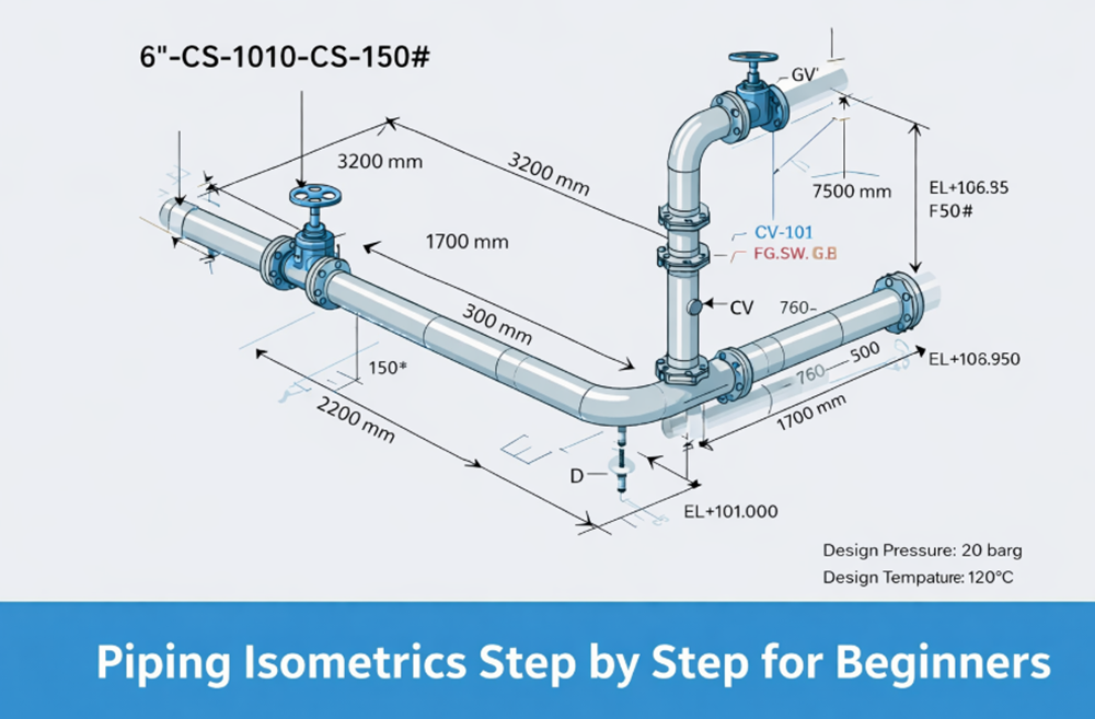
4. Dimensions and Elevations
All piping isometrics show centerline dimensions.
Key points:
- Horizontal dimensions
- Vertical elevations (EL +100.000, etc.)
- True pipe lengths for fabrication
👉 Fabricators do not calculate lengths — they cut exactly what is shown.
Step-by-Step Process to Create a Piping Isometric
Step 1: Study the P&ID Carefully
Before drawing anything:
- Identify line number
- Confirm piping class
- Check valve types and instruments
- Verify design pressure and temperature
Never assume. Always cross-check.
Step 2: Understand Plant Layout and Equipment Locations
From piping layout drawings or 3D model:
- Locate pumps, vessels, heat exchangers
- Identify nozzles and elevations
- Confirm pipe rack routing
Example:
Pump discharge nozzle at EL +100.500
Pipe rack bottom at EL +102.000
Step 3: Decide Pipe Routing
Good piping routing considers:
- Minimum bends
- Accessibility for operation
- Maintenance space
- Thermal expansion
In oil and gas piping, poor routing increases:
- Stress
- Support cost
- Installation time
Step 4: Draw the Isometric View
Piping isometrics use 30° angled axes:
- One vertical
- Two inclined at 30°
Key rules:
- No perspective distortion
- Dimensions are true lengths
- Flow direction is clearly marked
Step 5: Add Fittings, Valves, and Flanges
Each fitting must be clearly identified:
- Elbows (90°, 45°)
- Reducers (concentric / eccentric)
- Gate, globe, check valves
- Control valves
Valve tags must match P&ID numbers exactly.
Step 6: Show Welds and Spool Breaks
Weld numbering is critical for:
- NDT
- PWHT
- Hydrotest
Typical weld types shown:
- Field weld (FW)
- Shop weld (SW)
Spool breaks are decided based on:
- Transportation limits
- Site handling capacity
Practical Plant Example – Pump Discharge Line
Let us consider a pump discharge line in a power plant:
- Line Number: 8”-FW-204-CS-300#
- Fluid: Feedwater
- Design Pressure: 110 barg
- Design Temperature: 180°C
Isometric Will Show:
- Pump discharge nozzle elevation
- Flexible loop or expansion bend
- Check valve + gate valve
- Drain point at low elevation
- Vent near high point
This ensures:
- Safe operation
- Easy commissioning
- Compliance with ASME B31.1
Insulation and Tracing Information
Every piping isometric must specify:
Insulation:
- Type (Hot, Cold, Acoustic)
- Thickness (e.g., 50 mm)
Tracing:
- Steam tracing
- Electric heat tracing
Example note:
INSULATION: HOT, 50 MM
TRACING: STEAM TRACING REQUIRED
Missing insulation data causes serious construction delays.
Common Beginner Mistakes in Piping Isometrics
- Ignoring line number consistency
- Missing elevations
- Incorrect valve orientation
- Forgetting drains and vents
- Mixing piping classes
Avoiding these mistakes will immediately improve your piping design quality.
How Piping Isometrics Are Used on Site
Piping isometrics are used by:
- Fabrication shops
- Site erection teams
- QA/QC inspectors
- Commissioning engineers
They are also used for:
- Material take-off (MTO)
- Stress analysis input
- As-built documentation
Frequently Asked Questions (FAQ)
Q 1: What is a piping isometric drawing?
A piping isometric drawing is a three-dimensional representation of a piping line showing pipe routing, dimensions, fittings, valves, and weld details. It is used for pipe fabrication, erection, and inspection at site.
Q 2: How is a piping isometric different from a P&ID?
A P&ID shows process intent, flow direction, instruments, and control philosophy, while a piping isometric shows physical pipe routing with exact dimensions and elevations. Piping isometrics are prepared based on approved P&IDs.
Q 3: Why is line numbering important in piping isometrics?
The line numbering system links the piping isometric to the P&ID, line list, piping class, and material specification. Any error in line number can lead to wrong material procurement or fabrication mistakes.
Q 4: Which ASME code is commonly used for piping isometrics?
Piping isometrics follow project piping codes such as ASME B31.1 for power piping and ASME B31.3 for process piping. The selected ASME B31 code governs design pressure, design temperature, and allowable stresses.
Final Thoughts from a Senior Piping Engineer
Learning piping isometrics is not about drawing skills — it is about understanding how a plant is built and operated.
If you master:
- P&ID interpretation
- Line numbering system
- Piping class philosophy
- ASME B31 code intent
You will become a strong and reliable piping engineer, not just a draftsman.
Piping systems in power plants are designed according to ASME B31.1 as published by ASME.
🔗 Link to: