Understand flanges and fittings in piping engineering with this detailed beginner guide. The article explains piping class, flange ratings, design pressure, design temperature, and material specifications clearly. Real-world plant examples help you learn correct flange and fitting selection. Perfect for learning piping design basics as per industry practice.
Table of Contents
Introduction:
Why Flanges & Fittings Matter in Piping Engineering?
In every piping system—whether in oil & gas plants, chemical units, refineries, or power plants—flanges and fittings play a critical role. Pipes alone cannot change direction, connect equipment, or allow maintenance. That is where flanges and fittings come in.
As a piping engineer with more than 20 years of real-world experience, I have seen many piping failures, leaks, and construction delays caused not by pipe material, but by wrong selection or incorrect use of flanges and fittings.
This article explains flanges and fittings step by step, in simple language, while keeping standard piping engineering terms exactly as used in industry. If you are a beginner, junior engineer, or student, this guide will help you understand not just what flanges and fittings are, but why they are selected in a real plant.
Where Flanges & Fittings Fit in Piping Design?
Before selecting any flange or fitting, a piping engineer must understand the design basis of the line.
Every piping line is defined by:
- Line number
- Fluid code
- Design pressure
- Design temperature
- Operating pressure
- Operating temperature
- Material specification
- Piping class
- Corrosion allowance
- Insulation and tracing requirements
👉 Read also for better Understanding Line Numbering and Fluid Codes
Flanges and fittings are not selected independently. They are always selected as part of a piping class, which controls material, rating, and end connection.
What Are Flanges?
A flange is a mechanical component used to connect:
- Pipe to pipe
- Pipe to valve
- Pipe to equipment (pump, heat exchanger, turbine, vessel)
Flanges are joined using bolts, nuts, and a gasket, forming a flanged joint.
Why Flanges Are Used?
- Equipment needs to be removed for maintenance
- Valves require replacement
- Alignment flexibility during installation
- Inspection access in critical services
In high-temperature and high-pressure systems, flanges are used carefully because they are potential leak points.
Common Types of Flanges Used in Plants
1. Weld Neck Flange (WN)
The weld neck flange is the most commonly used flange in power plants and high-pressure piping.
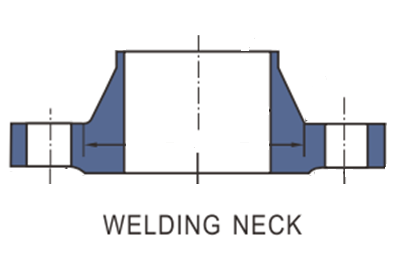
Key features:
- Long tapered hub
- Butt welded to the pipe
- Smooth stress distribution
Where used:
- Main steam lines
- Feedwater lines
- High-temperature services
Practical example:
A main steam line from boiler outlet to turbine inlet will almost always use weld neck flanges due to high design temperature and thermal expansion.
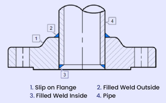
2. Slip-On Flange (SO)
In a slip-on flange, the pipe slides inside the flange and is fillet welded.
In a slip-on flange, the pipe slides inside the flange and is fillet welded.
Advantages:
- Easy to align
- Lower cost
Limitations:
- Lower strength than weld neck
- Not preferred for severe cyclic services
Typical use:
Low-pressure condensate or utility lines.
3. Socket Weld Flange (SW)
The pipe is inserted into a socket and fillet welded.
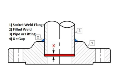
Important note:
Socket weld flanges create a crevice, which can lead to corrosion in wet services.
Used mainly for:
Small-bore piping with high pressure but low corrosion risk.
4. Blind Flange (BL)
A blind flange closes the end of a pipeline.
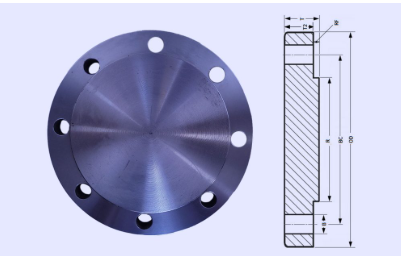
Common uses:
- Future line extension
- Isolation during hydrotest
- Equipment nozzle closure
Flange Facing Types
Flange facing is the surface where the gasket sits.
Common facing types:
- Raised Face (RF) – most common
- Flat Face (FF) – typically for cast iron equipment
- Ring Type Joint (RTJ) – very high pressure and temperature
Beginner mistake:
Using RF flange against FF equipment nozzle can damage the equipment flange.
Flange Rating and Pressure–Temperature Relationship
Flanges are classified as:
- Class 150
- Class 300
- Class 600
- Class 900
- Class 1500
- Class 2500
⚠️ Important concept:
Flange rating is not constant pressure. It depends on:
- Material
- Design temperature
For example:
- A Class 300 carbon steel flange at 38°C can handle much higher pressure than at 450°C.
👉 Internal link suggestion: Flange Rating and Pressure–Temperature Charts Explained
Flange Materials Used in Piping Systems
Common flange materials include:
- Carbon steel (ASTM A105)
- Alloy steel (ASTM A182 F11, F22)
- Stainless steel (ASTM A182 F304, F316)
- Special alloys for corrosive services
Rule of thumb:
Flange material should match pipe material specification defined in the piping class.
What Are Pipe Fittings?
Pipe fittings are components used to:
- Change direction
- Change pipe size
- Create branch connections
- Terminate a line
Without fittings, piping layout would be impossible.
Types of Pipe Fittings Explained Step by Step
Elbows
Used to change flow direction.
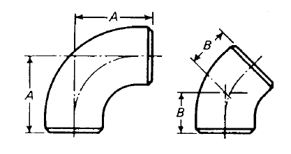
- 90° elbow
- 45° elbow
- Long radius (LR)
- Short radius (SR)
Design note:
Long radius elbows are preferred because they reduce:
- Pressure drop
- Stress concentration
Tees
Used for branch connections.
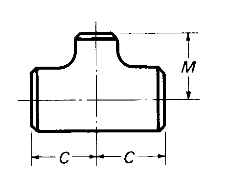
- Equal tee
- Reducing tee
Practical example:
A branch line supplying auxiliary steam is taken from a main header using a tee.
Reducers
Used to change pipe size.
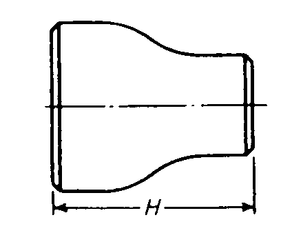
- Concentric reducer – centerline maintained
- Eccentric reducer – offset centerline
Key rule:
- Flat side up → vapor lines
- Flat side down → liquid lines
This avoids air pockets or liquid accumulation.
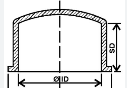
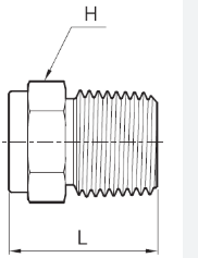
Caps and Plugs
- Caps close pipe ends permanently
- Plugs close threaded connections
Often used for future expansion or maintenance.
End Connections of Fittings
Fittings are available with:
- Butt weld ends
- Socket weld ends
- Threaded ends
Selection depends on:
- Design pressure
- Design temperature
- Line size
- Fluid code
High-pressure and high-temperature lines mostly use butt weld fittings.
Fitting Material Specifications
Common fitting material standards:
- ASTM A234 (carbon & alloy steel)
- ASTM A403 (stainless steel)
- ASTM A420 (low-temperature service)
Material must match:
- Pipe material
- Flange material
- Piping class
Flanges & Fittings in a Piping Class
A piping class is the backbone of piping design.
It defines:
- Pipe material and schedule
- Flange type and rating
- Fitting type and rating
- Valve type
- Gasket and bolting
Once a piping class is selected, the engineer must not mix components outside that class.
Common Beginner Mistakes
- Mixing different flange ratings in one line
- Using socket weld fittings in corrosive service
- Wrong reducer orientation
- Ignoring thermal expansion effects
- Assuming “higher rating is always safer”
Inspection and QA/QC Considerations
Before installation, flanges and fittings are checked for:
- Material test certificate (MTC)
- Heat number traceability
- Dimensions
- Visual defects
- Correct rating and material
Many site rejections happen due to material mismatch with piping class.
Practical Plant Example
Line number: MS-101
Fluid code: Steam
Design pressure: 110 bar
Design temperature: 540°C
Piping class: High-pressure alloy steel
Selection:
- Weld neck flanges, Class 900
- Alloy steel elbows and tees
- Butt weld end connections
Each selection is driven by pressure, temperature, and long-term creep considerations.
Frequently Asked Questions (FAQ)
Q 1: Why are weld neck flanges preferred in high-pressure lines?
Because they provide better stress distribution and perform well under thermal expansion and cyclic loads.
Q 2: What is the difference between concentric and eccentric reducers?
Concentric reducers maintain centerline; eccentric reducers prevent air or liquid accumulation.
Q 3: Can different flange ratings be mixed in one line?
No. The lowest rated component governs the line and mixing is not allowed.
Q 4: How do I select fitting material?
Fitting material must match pipe and flange material as defined in the piping class.
Key Takeaways for Beginners
- Flanges and fittings are critical safety components
- Selection is always governed by piping class
- Design pressure and design temperature control everything
- Practical plant experience matters as much as code knowledge
1 thought on “Piping Flanges and Fittings Explained as per Industry Practice”