Introduction
piping engineering practice, the terms piping and pipeline are often used incorrectly. However, from a design, code, and safety point of view, piping and pipeline are two different systems. Understanding this difference is essential for correct engineering decisions.
Table of Contents
What Is Piping?
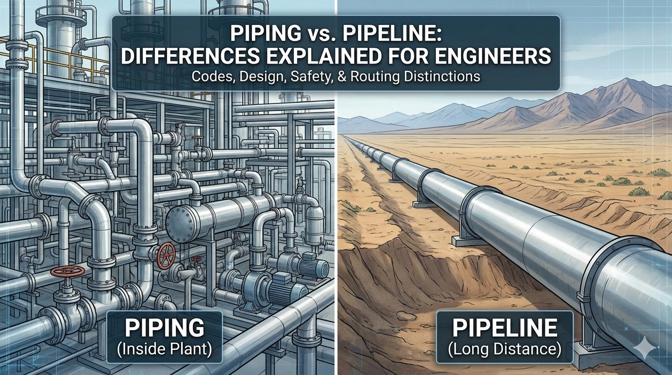
Piping is an engineered system used to transport fluids inside a plant or facility. Piping systems connect equipment such as pumps, vessels, heat exchangers, and compressors. These systems contain many fittings, valves, and supports and are designed for specific pressure, temperature, and service conditions.
What Is a Pipeline?
A pipeline is used to transport fluids over long distances, usually outside plant boundaries. Pipelines are generally straight, have very few fittings, and are often buried underground or laid above ground across long routes.
Why this distinction matters: Codes, design philosophy, inspection, and maintenance differ for each system. Misidentifying a system can lead to using the wrong code or the wrong mechanical design assumptions.
Key Differences Between Piping and Pipeline
Piping is installed inside plants, has complex routing, and uses many components. Pipelines are installed over long distances with simple routing and minimal components.
Applicable Codes and Standards
Piping and pipeline design follow different ASME standards:
- Piping systems inside plants are typically designed to ASME B31.3 (Process Piping) or ASME B31.1 (Power Piping) depending on service and power plant applications.
- Pipeline systems are governed by ASME B31.4 (Pipeline Transportation Systems for Liquids and Slurries) and ASME B31.8 (Gas Transmission and Distribution Piping Systems) for gas pipelines.
Practical tip: Early in a project, confirm which code applies. The code governs allowable stresses, flexibility requirements, design pressure/temperature rules, and testing requirements.
Design Philosophy: Layout, Flexibility, and Stress
- Piping: Plant piping often has complex routing with many components and restraints. Thermal expansion and multiple anchor/guide points create significant stress analysis work. Pipe stress engineers must model thermal growth, include expansion loops or anchors, and ensure support spacing and flexibility comply with ASME B31.3 or B31.1 criteria.
- Pipeline: Pipeline behavior is influenced by soil interaction and route continuity. Pipelines are long and straight; thermal expansion is accommodated over long runs and by trenching or bends. Stress analysis for pipelines focuses more on longitudinal forces, buckling (for elevated temperature or subsea), and soil-pipeline interaction rather than the localized flexibility solutions common in plant piping.
Design note: Treat piping as a highly restrained system with multiple boundary conditions. Treat pipeline as a continuous structure interacting with its environment.
Components and Complexity
Pipeline: Few fittings are used (mostly bends, tees at limited locations). Pigging stations, block valves, and metering stations are spaced along the route. Corrosion protection (coatings, cathodic protection) and right-of-way management are major concerns.
Piping: Many fittings, valves, and supports are common. Specialty items (e.g., orifice runs, control valves) require careful local design. The presence of equipment imposes tie-in constraints and often forces complex three-dimensional routing.
Materials and Corrosion Management
Material selection follows the fluid, temperature, pressure, and expected corrosion. For both piping and pipelines:
- Piping inside plants may require localized corrosion protection (liners, jackets) or corrosion-resistant alloys for severe service.
- Choose materials per corrosion allowance, H2S/CO2 content, and temperature limits.
- Apply protective measures: coatings, linings, corrosion inhibitors, or cathodic protection for buried pipelines.
Supports, Anchors, and Expansion
- Piping: Support design is critical. Supports must control vertical loads, limit vibration, and allow thermal movement. Anchors and guides create reaction forces that drive stress analysis. Use spring supports and expansion loops where needed.
- Pipeline: Supports are fewer; soil provides lateral restraint. Above-ground pipelines require structural supports and attention to differential movement between supports. Buried pipelines rely on trench backfill and bedding for load distribution.
Inspection, Testing, and Maintenance
- Piping: Frequent inspections, hydrostatic testing, and access for maintenance are standard. Plant piping is accessible and often requires periodic NDT, visual checks, and inline inspections for special services.
- Pipeline: Pipelines are tested in large sections and use pigging (intelligent pigs) for internal inspection. Right-of-way inspection, leak detection systems, and cathodic protection monitoring are routine.
Safety and Risk Considerations
- Piping: Higher component density and proximity to personnel require careful hazard analysis (HAZOP) and emergency relief systems sized per code. The design must consider potential jetting, BLEVE (for vessels), and flammable cloud dispersion.
- Pipeline: Long distance increases exposure to third-party damage (excavation), environmental sensitivity, and remote leaks. Emergency response planning and pipeline integrity management become critical.
Stress Analysis Methods and Best Practices
- Use finite element or dedicated pipe stress software to model piping systems with accurate boundary conditions and realistic thermal loads.
- Include weight, fluid mass, wind, seismic, and thermal effects per relevant codes.
- For pipelines, model longitudinal forces, lateral buckling, and soil interactions. Consider finite element continuum models for detailed subsea or high-temperature pipeline segments.
Common Mistakes and How to Avoid Them
- Applying the wrong code: Determine whether the system is piping or pipeline early in the project to select the correct standard.
- Underestimating thermal movement: Always model thermal growth and check support reactions.
- Ignoring corrosion protection: Both piping and pipelines need coherent corrosion management plans.
- Poor access planning: In-plant piping must allow maintenance access; pipelines must allow pigging and monitoring.
Example Case: Process Unit Tie-in vs Long-Haul Transfer
- Piping tie-in to a heat exchanger: Requires 3D routing in limited space, multiple supports, spring hangers for thermal movement, and local flexibility for nozzle loads.
- Long-haul crude transfer pipeline: Requires right-of-way clearance, block valves, pigging facilities, cathodic protection, and hydrostatic testing in large sections.
Reference Books and Further Reading
Useful books and standards to build mastery:
ASME Boiler and Pressure Vessel Code; ASME B31 series codes
Process Piping Design Handbook — M. W. Kellogg.
Piping Handbook — Mohinder Nayyar.
Pipe Stress Engineering — Liang-Chuan Peng.
1 thought on “Piping vs Pipeline: Differences Explained for Engineers”