Complete Guide to Pressure Vessel Design, Calculation, and Code Requirements
Learn ASME Section VIII Division 1 with practical examples. Understand design pressure, MAWP, thickness calculation, welding, hydrotest & vessel rules.
Pressure vessels are critical equipment in oil & gas plants, refineries, chemical industries, and power plants. Equipment such as separators, scrubbers, surge drums, reactors, columns, and heat exchangers operate under pressure and must be designed safely.
The governing code for most of these vessels is ASME Section VIII Division 1.
If you are learning piping engineering, working in mechanical design, QA/QC, or preparing for interviews, understanding ASME Section VIII Division 1 is essential. This guide explains the code in simple language while keeping correct technical terminology such as:
- Design pressure
- Design temperature
- MAWP
- Material specification
- Corrosion allowance
- Weld joint efficiency
- Line number
- Piping class
- Fluid code
- Insulation and tracing
This article is fully aligned with practical plant engineering and also connects with related topics like ASME Section II, ASME Section IX, pipe thickness calculations, welding, hydrotest, and inspection.
Table of Contents
What is ASME Section VIII Division 1?
ASME Section VIII Division 1 provides rules for the design, fabrication, inspection, testing, and certification of pressure vessels operating above 15 psi.
It follows a Design by Rule method, which means:
- Standard formulas are provided
- Conservative safety margins are used
- Thickness calculations are straightforward
- Advanced stress analysis is not mandatory
This division is widely used because it is practical, reliable, and globally accepted.
If you are already familiar with ASME B31.3 for process piping, you will notice many similarities in concepts like allowable stress, corrosion allowance, and design conditions.
Structure of ASME Section VIII Division 1
Division 1 is organized into three main subsections:
- Subsection A – General Requirements
- Subsection B – Methods of Fabrication
- Subsection C – Material-Specific Requirements
Let’s understand each section step by step.
1. Subsection A – General Requirements (UG Section)
This section contains the core rules applicable to all vessels.
1.1 Scope (UG-1)
This defines:
- Which vessels are covered
- Pressure limits
- Exclusions
For example:
A separator with:
- Design pressure = 20 barg
- Design temperature = 150°C
- Hydrocarbon service
Falls under ASME Section VIII Division 1.
However, atmospheric tanks follow API 650, not Section VIII.
1.2 Materials (UG-4 to UG-15)
This section specifies permitted materials and their material specification requirements.
Common vessel materials include:
- SA-516 Gr 70 (Carbon Steel)
- SA-387 (Alloy Steel)
- SA-240 TP304 / TP316 (Stainless Steel)
Material properties such as allowable stress are taken from ASME Section II.
If you are learning about pipe materials and corrosion allowance, you should also review:
- Pipe Materials
- Corrosion Allowance
- ASME Section II
These concepts directly apply to vessel design.
Important Concepts
- Material Test Certificate (MTC)
- Impact testing (Charpy)
- Temperature limitations
- Bolting materials
Material selection always depends on:
- Fluid code
- Corrosion rate
- Design temperature
- Operating pressure
2. Design Requirements (UG-16 to UG-101)
This is the most important part of ASME Section VIII Division 1.
2.1 Design Pressure (UG-21)
Design pressure is the maximum pressure used for thickness calculation.
It must be higher than normal operating pressure.
Practical Coordination with Piping
If vessel design pressure = 25 barg
Then connected piping class must be rated accordingly.
This connects directly with:
- Flange Rating
- Line Designation
- ASME B16 Standards
A mismatch between vessel design pressure and piping class rating can cause serious safety issues.
2.2 Design Temperature (UG-20)
Design temperature is the maximum metal temperature expected.
It affects:
- Allowable stress
- Material selection
- Thickness calculation
Higher temperature → Lower allowable stress → Higher thickness.
2.3 Maximum Allowable Stress (UG-23)
Allowable stress values are taken from ASME Section II.
These values are essential for:
- Shell thickness calculation
- Head thickness
- Nozzle design
If you want deeper understanding, review:
- Pipe Thickness Calculation
- Allowable Stress Concept
3. Shell Thickness Under Internal Pressure (UG-27)
For cylindrical shells, thickness depends on:
- Design pressure
- Inside radius
- Allowable stress
- Weld joint efficiency
- Corrosion allowance
Example
Gas separator:
Design pressure = 18 barg
Material = SA-516 Gr 70
Joint efficiency = 0.85
Corrosion allowance = 3 mm
Calculated thickness = Pressure thickness + Corrosion allowance.
This concept is similar to pipe thickness calculation in ASME B31.3.
4. Shell Under External Pressure (UG-28)
External pressure design is required for:
- Vacuum service
- Tall columns
- Steam-out conditions
Unlike internal pressure, external pressure can cause buckling.
Charts are used instead of simple formulas.
If you are studying Stress Basics or Pipe Stress, understanding buckling behavior is very useful here.
5. Heads and Closures (UG-32 to UG-35)
Common head types used in pressure vessels:
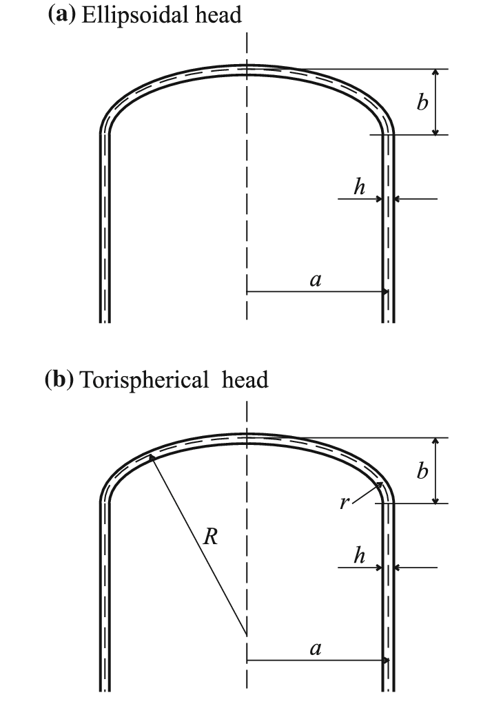


Types of Heads
- 2:1 Ellipsoidal head
- Torispherical head
- Hemispherical head
- Flat head
Hemispherical heads require minimum thickness but are expensive to fabricate.
Ellipsoidal heads are most common in separators and drums.
6. Openings and Reinforcement (UG-36 to UG-46)
When a nozzle opening is made, metal is removed from the shell.
The code requires reinforcement to compensate for lost area.
Reinforcement methods:
- Excess shell thickness
- Reinforcement pad (repad)
- Insert plate
This connects directly with:
- Piping Components
- Flanges & Fittings
- Valve Selection
Whenever a new line number is added to a vessel, the nozzle design must be reviewed carefully.
7. Welding Requirements (UW Section)
This section governs:
- Weld joint categories
- Joint efficiency
- Welding procedure qualification
- Welder qualification
Welding procedures must comply with ASME Section IX.
Joint Categories
- Category A – Longitudinal weld
- Category B – Circumferential weld
- Category C – Flange weld
- Category D – Nozzle weld
Joint efficiency affects thickness. Lower efficiency → Higher thickness required.
8. Heat Treatment (UG-85)
Post Weld Heat Treatment (PWHT) may be required depending on:
- Material specification
- Thickness
- Service conditions
Cr-Mo alloy vessels almost always require PWHT.
This connects with:
- Welding
- Fabrication
- Inspection
9. Inspection and Testing (UG-90 to UG-103)
Includes:
- Visual inspection
- Radiography (RT)
- Ultrasonic testing (UT)
- Magnetic particle testing (MT)
- Dye penetrant testing (PT)
These topics are directly related to:
- Inspection
- QA/QC Engineer Role
- Hydrotest
Hydrostatic Test (UG-99)
Hydrotest pressure is typically 1.3 × MAWP (with temperature correction).
Hydrotest ensures structural integrity before commissioning.
For stainless steel vessels:
- Chloride content in test water must be controlled
- Proper drying required after testing
Pneumatic Test (UG-100)
Used when hydrotest is not practical.
Requires strict safety precautions.
10. Pressure Relief Devices (UG-125 to UG-137)
Every vessel must be protected against overpressure.
Protection devices include:
- Pressure Relief Valve (PRV)
- Rupture disc
- Combination devices
Relief valve installation must consider:
- Back pressure
- Piping class
- Line routing
- Supports
- Insulation and tracing
This connects with:
- Piping Layout Rules
- Pipe Supports
- Stress Basics
11. Marking and Certification (UG-115 to UG-120)
After fabrication and testing:
- Vessel is stamped with U-Stamp
- Nameplate attached
- Manufacturer’s Data Report prepared
Nameplate includes:
- MAWP
- Design temperature
- Serial number
- Year of manufacture
This is the legal certification of the vessel.
How ASME Section VIII Division 1 Connects with Piping Engineering
As a piping engineer, always verify:
- Vessel design pressure vs piping class rating
- Nozzle flange rating
- Corrosion allowance compatibility
- Fluid code suitability
- Insulation clearance
- Tracing requirements
Understanding this code strengthens your knowledge in:
- Piping Design
- Pipe Stress & Supports
- Construction & QA/QC
- Interview Q&A
Best 4 FAQs – ASME Section VIII Division 1
1. What is the difference between Design Pressure and MAWP?
Design pressure is used for thickness calculation.
MAWP is the maximum pressure allowed at design temperature after fabrication.
2. Is hydrotest mandatory in ASME Section VIII Division 1?
Yes, hydrostatic testing is generally mandatory unless pneumatic testing is justified and approved.
3. How does weld joint efficiency affect thickness?
Lower joint efficiency increases required thickness because allowable stress is effectively reduced.
4. How is ASME Section VIII different from ASME B31.3?
ASME Section VIII applies to pressure vessels.
ASME B31.3 applies to process piping systems.
Final Thoughts
ASME Section VIII Division 1 is the foundation of safe pressure vessel design in process industries.
If you clearly understand:
- Design pressure
- Design temperature
- Allowable stress
- Thickness calculation
- Reinforcement rules
- Inspection and hydrotest requirements
You will confidently handle vessel and piping coordination in real projects.
For deeper learning, continue exploring related topics such as:
- ASME Section II
- ASME Section IX
- Pipe Thickness Calculation
- Flange Rating
- Stress Basics
- Hydrotest and Inspection
Mastering these connected topics builds strong practical knowledge in piping engineering and pressure vessel design.