Introduction
In piping design and piping engineering, correct identification of every pipeline is extremely important. In large plants such as oil & gas facilities, chemical plants, refineries, and power plants, thousands of pipelines carry different fluids under different pressures and temperatures.
To manage this complexity, piping engineers use a Line Designation system, also known as the Line Numbering System. This system ensures clarity, safety, and consistency across all engineering drawings and documents.
Table of Contents
What is Line Designation in Piping Design
Line Designation is a unique identification code assigned to each pipeline in a piping system. It provides essential design and service information about the pipe in a short, standardized format.
A line designation typically communicates:
- Pipe size (NPS or DN)
- Fluid code or service
- Design pressure and pressure class
- Piping class and material specification
- Requirements like insulation, heat tracing, or special service
Line designation is used on:
- P&IDs
- Piping isometric drawings
- Line lists
- Stress analysis documents
- Construction and commissioning drawings
Why Line Designation is Important
Line designation plays a key role in piping engineering design and execution.
Key reasons why line designation is critical:
- Ensures correct piping material selection
- Helps define design pressure and design temperature
- Avoids mixing of process, utility, and hazardous lines
- Supports pipe stress analysis and flexibility design
- Ensures compliance with ASME B31 piping codes
- Helps construction and QA/QC teams avoid costly mistakes
Without a proper line designation system, even a well-designed plant can face serious safety and operational issues.
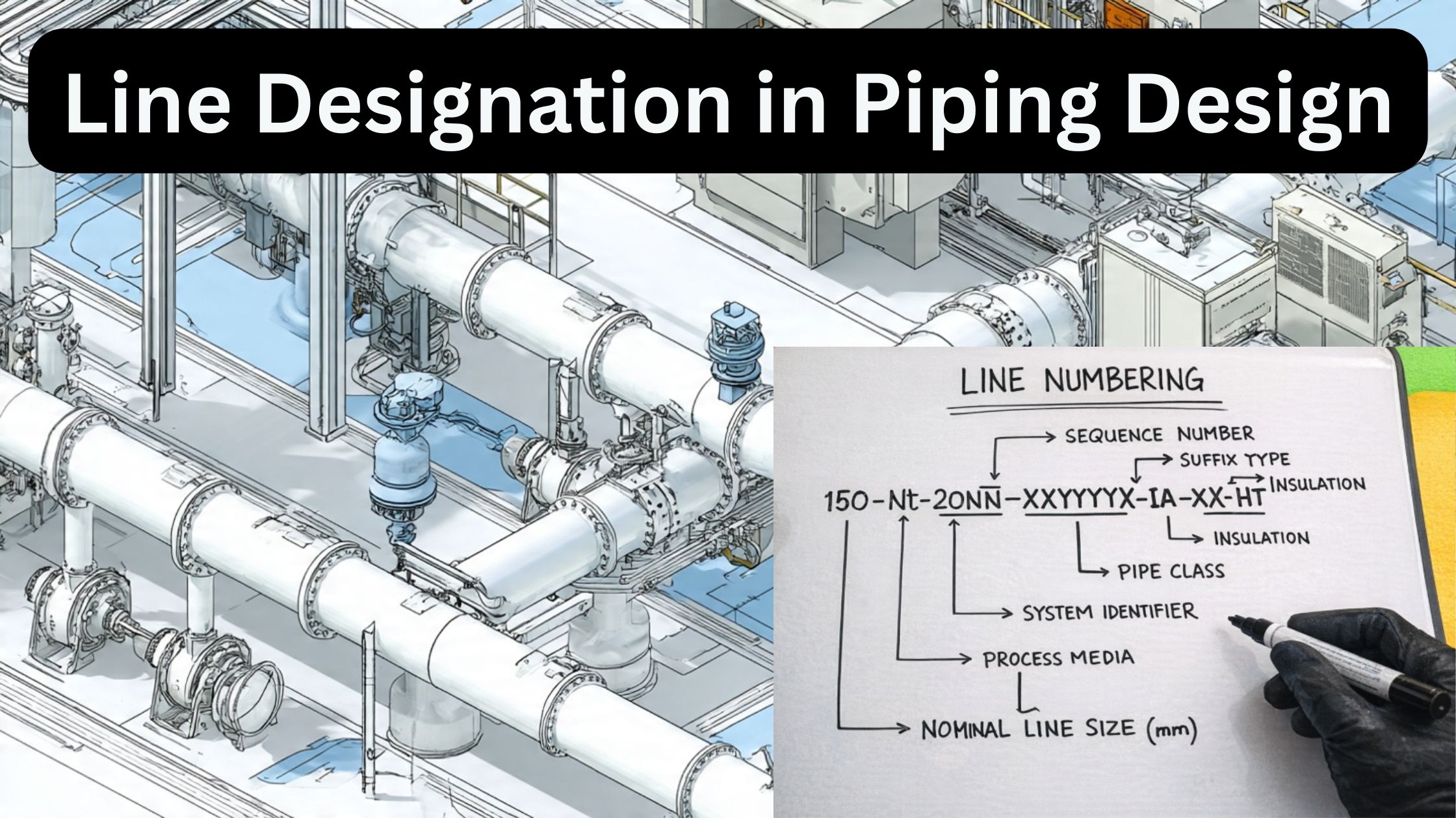
Typical Line Designation Format
Each project defines its own line numbering philosophy, but most follow a similar pattern.
Typical Line Designation Example
Typical Line Designation Format Each project defines its own line numbering philosophy, but most follow a similar pattern.
Typical Line Designation Example:
10″-P-150-CS-A1-H
Another commonly used format in oil & gas projects:
6″-FG-300-SS316-LT-INS
line numbering system in piping
Explanation of Each Part of a Line Number
Let us break down a typical line designation used in oil and gas piping systems.
1. Nominal Pipe Size (NPS / DN)
Examples:
10"→ 10-inch nominal pipe sizeDN150→ Metric pipe size
Pipe size is selected based on process flow requirements and hydraulic calculations.
2. Fluid Code / Service Code
Examples:
P→ Process fluidFG→ Fuel GasCW→ Cooling WaterST→ Steam
Fluid codes are defined by the process engineering team and shown first on the P&ID.
3. Design Pressure / Pressure Class
Examples:
150→ ASME Class 150300→ ASME Class 300
Pressure class is selected based on design pressure and design temperature as per ASME B16 standards.
4. Material Specification and Piping Class
Examples:
CS→ Carbon SteelSS316→ Stainless Steel 316A1,LT,HT→ Project-specific piping class codes
The piping class defines:
- Pipe and fitting material
- Flange rating
- Corrosion allowance
- Gasket and bolting material
5. Insulation, Tracing, and Special Requirements
Examples:
INS→ Insulated lineHT→ Heat tracedH→ Hot serviceNACE→ Sour service requirement
These requirements are important for operation, safety, and maintenance.
👉 (Suggested internal link)
thermal expansion in piping [LINK → Thermal Expansion]
Example of Line Designation from Oil & Gas / Process Plant
Example Line Number
8″-FG-300-CS-A1-HT
Explanation:
8"→ Pipe sizeFG→ Fuel Gas service300→ ASME Class 300CS→ Carbon Steel materialA1→ Project piping classHT→ Heat traced line
Such a line is typically used in fuel gas systems for heaters or gas turbines in oil & gas plants.
Common Mistakes in Line Designation
Even experienced engineers make mistakes if proper checks are not followed.
Common issues include:
- Wrong fluid code shown on P&ID
- Incorrect piping class selection
- Missing insulation or heat tracing requirement
- Mismatch between P&ID and piping isometrics
- Outdated line numbers after process changes
Relation with P&ID and Piping Isometrics
- P&ID is the master document where line designation is first assigned
- The same line number must appear on:
- Piping isometric drawings
- Stress analysis models
- Line list and MTO documents
Any change in line designation must be updated across all piping documents.
Applicable Codes and Standards (ASME B31 Series)
Line designation is closely linked to piping design codes, mainly:
- ASME B31.3 – Process Piping
- ASME B31.1 – Power Piping
- ASME B31.4 – Liquid Pipelines
- ASME B31.8 – Gas Transmission and Distribution
These codes define design pressure, temperature limits, material requirements, and allowable stresses.
FAQ
1: What is line designation in piping design?
Line designation is a unique identification code given to each pipeline. It shows important information such as pipe size, fluid service, piping class, design pressure, and special requirements like insulation or heat tracing.
2: Where is line designation used in piping engineering?
Line designation is mainly used on P&IDs, piping isometric drawings, line lists, and construction drawings to ensure correct material selection, safe design, and smooth construction.
3: Why is line designation important in oil and gas piping?
In oil and gas piping systems, line designation helps engineers identify hazardous services, select the correct piping class, comply with ASME B31 codes, and avoid errors during design, construction, and maintenance.
Conclusion
Line Designation in Piping Design is one of the most fundamental concepts in piping engineering. It acts as the identity card of a pipeline, clearly defining its size, service, material, pressure class, and special requirements.
For students, site engineers, and design engineers working with P&IDs, piping isometrics, and oil and gas piping systems, a strong understanding of line designation is essential for safe and efficient plant design.
3 thoughts on “What is Line Designation in Piping Design? Complete Guide for Engineers”