Learn ASME Section VIII Division 2 in simple English with practical engineering examples. Understand Design by Analysis (DBA), allowable stress, MAWP, fatigue analysis, material selection, and how Division 2 differs from Division 1.
Table of Contents
Introduction
Pressure vessels are among the most critical pieces of equipment in industries such as oil and gas, petrochemicals, LNG, fertilizers, and power generation. They are designed to safely contain fluids under pressure, often at high temperatures and in demanding operating conditions.
For many standard applications, engineers use ASME Section VIII Division 1, which provides straightforward design formulas based on the Design by Rule (DBR) approach. This method is reliable, widely accepted, and suitable for most pressure vessels.
However, not every vessel is “standard.” Imagine designing a hydrocracker reactor operating at 180 bar and 450°C. If you use Division 1, the calculated shell thickness may become very large. A thicker shell means more steel, longer welding time, higher transportation costs, and increased fabrication expenses.
This is where ASME Section VIII Division 2 becomes valuable.
Instead of relying mainly on conservative design formulas, Division 2 allows engineers to perform detailed stress analysis to optimize the design while maintaining the same level of safety. The result is often a lighter, more economical pressure vessel without compromising reliability.
Although Division 2 requires more engineering effort, it is commonly selected for high-pressure and critical-service equipment because it provides greater design flexibility and better material utilization.
In this guide, you’ll learn:
- What ASME Section VIII Division 2 is
- When it should be used
- How it differs from Division 1
- The basic structure of the code
- The difference between Design by Rule and Design by Analysis
In the following parts of this guide, we’ll also cover fatigue analysis, allowable stress, MAWP, hydrostatic testing, fabrication requirements, and how Division 2 affects piping engineering.
What is ASME Section VIII Division 2?
ASME Section VIII Division 2 is one of the design codes within the ASME Boiler and Pressure Vessel Code for the design and construction of pressure vessels.
Its main purpose is to provide more detailed engineering rules for vessels that operate under severe conditions.
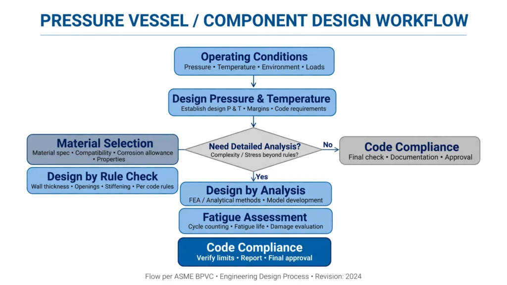
Unlike Division 1, which mainly relies on design equations, Division 2 combines traditional design formulas with detailed engineering analysis.
Think of it this way.
Suppose two engineers are designing the same pressure vessel.
The first engineer follows standard design equations and selects a conservative wall thickness.
The second engineer builds a computer model, studies how stresses are distributed throughout the vessel, evaluates thermal expansion, checks fatigue life, and optimizes the design.
Both designs can be safe.
The difference is that the second engineer understands exactly how the vessel behaves under operating conditions.
That is the philosophy behind Design by Analysis (DBA).
Key Features of Division 2
| Feature | Division 2 Approach |
| Design philosophy | Design by Rule + Design by Analysis |
| Allowable stress | Higher than Division 1 |
| Stress evaluation | Detailed stress classification |
| Fatigue analysis | Required for many cyclic services |
| FEA | Frequently used for complex components |
| Fabrication | More stringent quality requirements |
| Documentation | More comprehensive engineering records |
Why Was Division 2 Developed?
Many pressure vessels operate under conditions that are far more demanding than those assumed by simple design equations.
Examples include:
- High-pressure reactors
- LNG processing equipment
- Thick-wall pressure vessels
- High-temperature separators
- Critical chemical reactors
For these applications, engineers need more than minimum wall thickness calculations. They must understand how the vessel behaves during:
- Startup
- Shutdown
- Pressure fluctuations
- Temperature changes
- External loads
- Thermal expansion
Division 2 was developed to address these challenges by allowing detailed stress evaluation and optimized designs.
Instead of simply increasing the vessel thickness, engineers can demonstrate that the design is safe through analysis.
This often reduces the overall weight of the equipment while maintaining the required safety margin.
Also read this
- What is Piping? → https://mypipingnotes.com/what-is-piping/
- Pipe Thickness → https://mypipingnotes.com/pipe-thickness/
When Should You Choose Division 2 Instead of Division 1?
One of the most common questions among young engineers is:
“If Division 1 is already safe, why would anyone choose Division 2?”
The answer is simple.
Division 2 is not intended to replace Division 1.
Instead, it provides an alternative design method for situations where a more detailed engineering analysis can lead to a better overall design.
Typical applications include:
| Equipment | Why Division 2 Is Preferred |
| Hydrocracker reactors | Very high operating pressure |
| Ammonia converters | Thick-wall construction |
| LNG vessels | Low-temperature service |
| High-pressure separators | Cyclic pressure loading |
| Reactor vessels | Frequent thermal cycles |
| Critical heat exchangers | Material optimization |
For example, if a vessel designed using Division 1 requires a shell thickness of 110 mm, a detailed Division 2 analysis may show that a thickness of 95 mm is sufficient while still satisfying all code requirements.
Although the reduction may seem small, it can save several tonnes of steel on a large reactor.
That reduction lowers:
- Material cost
- Welding time
- PWHT duration
- Transportation weight
- Installation cost
For large refinery projects, these savings can be significant.
Real Engineering Example
Imagine you are designing a high-pressure separator for a refinery expansion project.
The design pressure is 150 bar, and the vessel diameter is 3.5 meters.
Using Division 1, the calculated shell thickness becomes very heavy because of conservative allowable stress values.
Using Division 2, the engineer performs detailed stress analysis, evaluates local nozzle stresses, checks fatigue life, and verifies stress limits.
The final design uses less material while meeting all safety requirements.
This is why many EPC companies select Division 2 for large, high-value equipment.
Structure of ASME Section VIII Division 2
Before learning the detailed design rules, it’s helpful to understand how the code is organized.
Each part focuses on a different stage of pressure vessel design and construction.
| Part | Main Purpose |
| Part 1 | General requirements |
| Part 2 | Responsibilities and duties |
| Part 3 | Material requirements |
| Part 4 | Design by Rule (DBR) |
| Part 5 | Design by Analysis (DBA) |
| Part 6 | Fabrication requirements |
| Part 7 | Inspection and testing |
| Part 8 | Pressure relief devices |
| Part 9 | Overpressure protection by system design |
Don’t worry about memorizing these sections.
As we continue through this guide, we’ll explain each important part using practical engineering examples.
What’s Coming Next?
Now that you understand what Division 2 is, why it was developed, and when it should be used, the next step is learning how it actually works.
In next post, we’ll cover:
- Design by Rule vs Design by Analysis
- Stress classification (Primary, Secondary, and Peak Stress)
- Allowable stress
- MAWP
- Design pressure and design temperature
- Corrosion allowance
- Material selection
These topics form the foundation of pressure vessel engineering and will make the more advanced sections on fatigue analysis and hydrotesting much easier to understand.